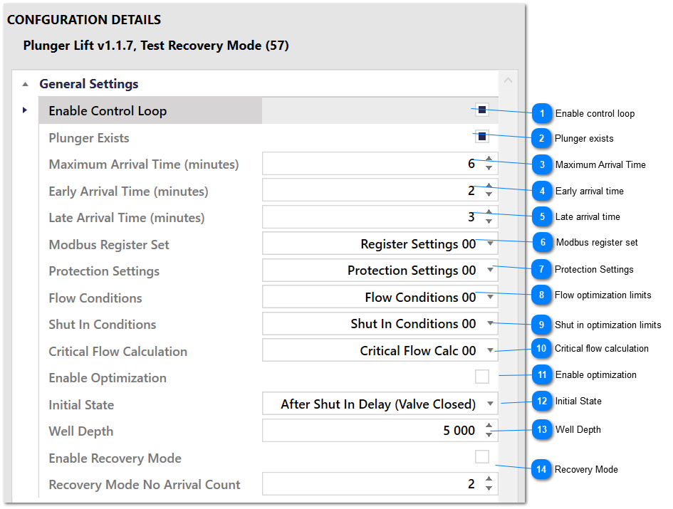
Plunger Control Settings are used to configure a plunger control loop. From here, you can enable a control loop, choose which conditions to use, enable optimization and choose Protection Settings.
When 1 plunger control loop is licensed, only Plunger Control 00 will work and the other control loops will be disabled. When 2 control loops are licensed, Plunger Control 00 and Plunger Control 01 will work. In other words control loop licenses are applied to specific loops.
Each enabled Plunger Control loop must reference a different Register Settings group. If two control loops share the same Registers Settings then register contention will occur. If a control loop is not enabled then the Register Settings do not matter.
Plunger Control Settings - Configuration Parameters
Enable control loop
Check this option to enable this control loop. The control loop will only execute if enabled.
If the well has a plunger, then this is the maximum time to wait for plunger arrival. If the plunger does not arrive within this time after flow conditions are met and the well is allowed to flow, the well will be shut in and the control algorithm will go to the After Shut in Delay state. This setting has no effect if the well does not have a plunger.
Set the Early Arrival Time limit here. If the plunger arrives in less than this time, the plunger arrival will be considered early. The optimization algorithm strives for normal plunger arrival, so if optimization is enabled choose this value with care.
Set the Late Arrival Time limit here. If the plunger arrives in greater than this time, the plunger arrival will be considered late. The optimization algorithm strives for normal plunger arrival, so if optimization is enabled choose this value with care.
Use this setting to select a set of optimization limits for this set of Flow Conditions. This setting has no effect if Enable Optimization is not enabled. See the Optimization sub section in the Operational Details section for information on how automatic optimization works.
Use this setting to select a set of optimization limits for this set of Shut In Conditions. This setting has no effect if Enable Optimization is not enabled. See the Optimization sub section in the Operational Details section for information on how automatic optimization works.
Choose the initial state for the control algorithm here. When the control loop is first enabled, or after a reset command is issued, the control algorithm will go to this state.
Enter the depth of the well here to that the Total Plunger Travel can be calculated. This setting has no effect on anything other than the total plunger travel calculation.
Use these settings to configure recovery mode. Recovery mode allows the value of the Minimum Off Time flow condition to be adjusted if the number of consecutive plunger no arrivals exceeds the value of Recovery Mode No Arrival Count. The value of the Minimum Off Time condition during recovery mode can be set via the Minimum Off Time Recovery setting.
Once entered, the Minimum Off Time condition will continue to use the Minimum Off Time Recovery value until the plunger arrives or until recovery mode is disabled. Once the plunger arrives or recovery mode is disabled, the Minimum Off Time condition will go back to using the normal value. The Minimum Off Time Recovery setting will not be adjusted if optimization is enabled.