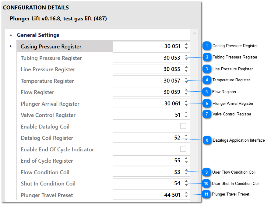
Use settings in this group to map Modbus registers to values that the application needs. All of the registers in this section are read, however, values that are not needed are ignored by the Plunger Lift application and not used in any way. In other words, if no conditions that depend on flow are needed, the Flow Register can hold any garbage value without upsetting the application. The opposite is also true, however. If conditions that require flow are enabled, you must map the Flow Register correctly.
Gas Lift modes that use critical flow will also require these registers to be configured correctly. This is so that the critical flow rate can be calculated correctly and so that the well flow rate is accurate and can be fed back into the PID loop that controls the position of the injection valve.
Units are not explicitly specified for any values in this section, since the values and condition limits must all be in the same units.
Up to 8 Input Output Register Settings instance are available.
All Input/Output Register Settings group have the same default registers, including the control valve register. If more than one control loop is enabled, the valve control register MUST be mapped to unique registers.
Enter the register that holds the casing pressure as a floating point value here. The next register will also be read. The casing pressure is required for numerous Flow Conditions and Shut In Conditions as well as the load ratio calculation.
Enter the register that holds the tubing pressure as a floating point value here. The next register will also be read. The tubing pressure is required for numerous Flow Conditions and Shut In Conditions as well as the load ratio calculation.
Enter the register that holds the line pressure as a floating point value here. The next register will also be read. The line pressure is required for numerous Flow Conditions and Shut In Conditions, as well as the load ratio calculation. It is also used in the Low Line PressureProtection Settings and the High Line Pressure Protection Settings.
Temperature is only required for the critical flow calculation, and even then, only if the Use Fixed Temperature option is not enabled in the Critical Flow Calculation settings. Temperature is not used in any Flow Conditions or Shut In Conditions
Enter the register that holds the flow from the well as a floating point value here. The next register will also be read. The flow from the well is required for numerous Flow Conditions and Shut In Conditions and for gas lift modes that use critical flow to calculate the injection flow rate set point.
If the well has a plunger, enter the register that holds the counter value that is tied to the plunger arrival sensor here. The application expects that this value will be incremented by 1 or many counts every time that the plunger arrives.
Enter the register that is tied to the sales valve here. The application will control the digital value in this register to 0 when the well should be shut in and to 1 when the well should flow.
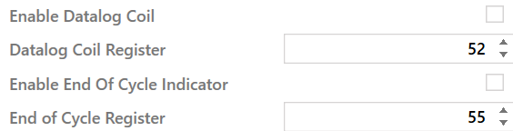
These settings are used to interface the Plunger Lift application to the SCADASuite Datalogs application. When the Enable Datalog Coil option is enabled, the register in the Datalog Coil Register will be set to 1 when all flow conditions are met, when the plunger arrives, and when a shut in condition is met. This allows for a Datalog write to be requested on demand, when an interesting event occurs. The Datalogs application will clear the coil when the request is processed.
When the Enable Datalog Coil option is not enabled, the Datalog Coil Register will not be used.
When the Enable End of CycleIndicator option is enabled, the register in the End of Cycle Register will be set for 10 seconds when a plunger control cycle is complete. The register will be set after the historic registers are updated. This functionality can be used to trigger a datalog write to capture history from the plunger control cycle that has just finished.
When the Enable End of CycleIndicator is not enabled, the End of Cycle Register will not be used.
Specify a Modbus coil register than can be used to control the User Flow Condition. When the value in this register is 1, the User Flow Condition will be met. When the value is in this register is 0, the User Flow Condition will not be met.
Specify a Modbus coil register that can be used to control the User Shut In Condition. When the value in this register is 1, the User Shut In Condition will be met. When the value in this register is 0, the User Shut In Condition will not be met.
The floating point value in the Plunger Travel Preset register, and the next register, will be incremented by twice the well depth for every plunger cycle. The new value will be written back out to this set of registers. Set the value in these registers to 0 when a new plunger is installed, or set the value in this register to some other value when the total plunger travel should be calculated from some known starting value.