The critical velocity of a gas well is the velocity at which liquids (water and condensate) are carried up and out of the well. The most commonly used calculation for critical velocity is the one developed by Turner. Turner's equation is a correlation based on measured results. A nearly identical correlation, called the Coleman equation, was developed for wells with a surface pressure of less than 1000 psi.
The critical velocity can be converted into a critical flow rate if the diameter of the well bore is known. By comparing the actual flow from the well to the calculated critical flow rate, we can be sure that the well is always flowing above the critical velocity and have some assurance that liquids are being removed from the well.
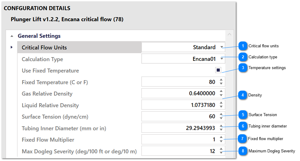
The Plunger Lift application supports calculation of the critical velocity using either Turner's or Coleman's equation. Settings in the Critical Flow Calculation group control how the value of critical flow is calculated.
The critical flow is only calculated if the Critical Flow shut in condition is enabled. If this condition is not enabled, critical flow is not needed, and is not calculated to reduce load on the RTU.
Choose the units set here. The application needs to know the units to correctly calculate critical flow.
When Metric is chosen, pressure should be in kPa, temperature should be in C and the tubing diameter should be in mm. The calculated flow will be in e3m3/day.
When Standard is chosen, pressure should be in psi, temperature should be in F and the tubing diameter should be in inches. The calculated flow will be in Mscf/day.
Care should be taken to make sure that units of the calculated flow match the units of flow from the flow computer. The Fixed Flow Multiplier setting can be used to make a correction, or the correction can be made in a ladder logic program.
Choose between using the Turner calculation, Coleman calculation, or a customer specific calculation. The Coleman calculation is recommended for use where the surface pressure is less than 1000 psi.
The Encana01 calculation is computationally intensive and should only be used when absolutely required.
Enable the Use Fixed Temperature option to fix the temperature used in the critical flow calculation to the value in the Fixed Temperature field. When the Use Fixed Temperature option is not enabled, the temperature is read from the Temperature Register on the Input/Output Modbus Register Settings group that is used by the plunger control loop.
The calculated critical flow is multiplied by the value in this field to come up with a new critical flow value that is used by the application. Use this field to implement a fixed multiplier to account for units conversion, additional margin, etc. Set this value to 1 so that it has no effect.