Use the settings in this section to enable or disable shut in conditions, and to adjust a condition's set point. Shut In Conditions are used to determine when to close the sales valve and shut the well in. The well is shut in when any enabled shut in condition is accepted. Conditions are evaluated when the plunger control loop is in the Wait To Shut In state. When any enabled shut in condition is met, the well will be shut in and the plunger lift control loop will move to the After Shut In Delay state.
Each shut in condition, except for the Maximum On Time condition, has an associated configurable delay. This delay is implemented between the time that the condition is first met and then subsequently accepted. If the condition is no longer met during the delay period, the delay timer is reset and the program waits again for the condition to be met.
The delay is used to prevent a short term upset from making a condition appear as if it is met. The delay can be disabled by setting it to 0.
For example, if the value of Minimum Flow is 500, and the Minimum Flow Delay is 30, the actual flow must be less than 500 for 30 seconds before the condition is accepted.
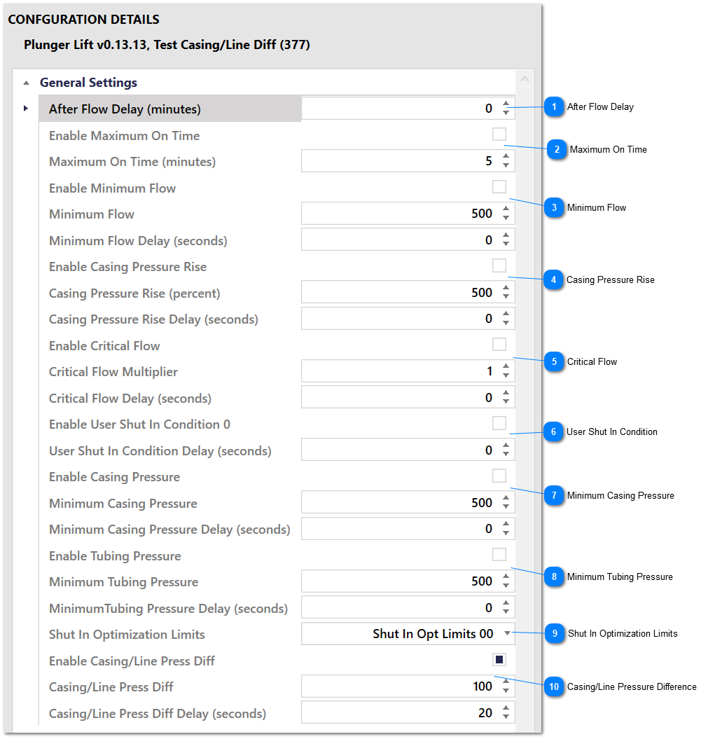
Shut In Conditions
After Flow Delay
Specify a fixed delay between when the well flows and when shut in conditions start being evaluated. This allows the well to settle before shut in conditions are evaluated. If the well has a plunger then this delay occurs after the plunger arrives. If the well doesn't have a plunger then this delay occurs immediately after all enabled flow conditions are met.
The Maximum On Time condition sets a maximum amount of time for the well to be allowed to flow. This condition has no delay, since it's already a delay. Timing starts from when the After Flow Delay expires.
This condition is accepted when the casing pressure rises from the minimum value for this cycle by more than the Casing Pressure Rise value as a percentage. The minimum casing pressure is tracked for each plunger control cycle. The value is cleared when entering the Waiting to Shut In control state.
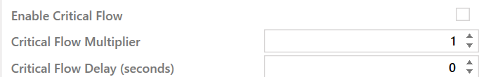
This condition is accepted when the actual flow is less than than the calculated critical flow multiplied by the Critical Flow Multiplier. The Critical Flow Multiplier lets you set some margin on top of the calculated critical flow.
For example, if the calculated critical flow value is 15, and the Critical Flow Multiplier is 2.5, the well will be shut in when the flow drops below 15 * 2.5 = 37.5. The Critical Flow Multiplier value can also be adjusted by the optimization algorithm, whereas the critical flow value itself is a calculated value and is constantly changing.
The User Shut In Condition allows for custom user ladder logic to drive a shut in condition. The condition is tied to a Modbus coil register that is specified in theInput/Output Modbus Registers Settings group that is used by the control loop. When the associated register is set to 1, the condition will be met. When the associated register is cleared, the condition will not be met.
Use this setting to select a set of optimization limits for this set of Shut In Conditions. This setting has no effect if Enable Optimization is not enabled. See the Optimization sub section in the Operational Details section for information on how automatic optimization works.