The Plunger Lift application includes a basic simulator that allows for some basic testing without needing a well. The simulator allows for the creation of simulated pressures, temperature, and flow. It is also possible to simulate plunger arrival. Simulated values are not meant to simulate a real well. Simulated values are meant to create some changing values to do some simple testing with.
Simulated values are written to the appropriate Modbus registers as configured on the referenced Input/Output Modbus Register Settings on the Plunger Control settings.
Simulation Settings are used to control the configuration of the simulator. Simulation 00 settings are used for Plunger Control 00, Simulation 01 settings are used for Plunger Control 01 and so on.
Simulation should be used with caution. When simulation is enabled accidentally, real values in Modbus registers could be overwritten, leading to undesirable operation.
Simulation settings can be reset by downloading the application's configuration to the RTU. No changes are required. Simply downloading the configuration is sufficient.
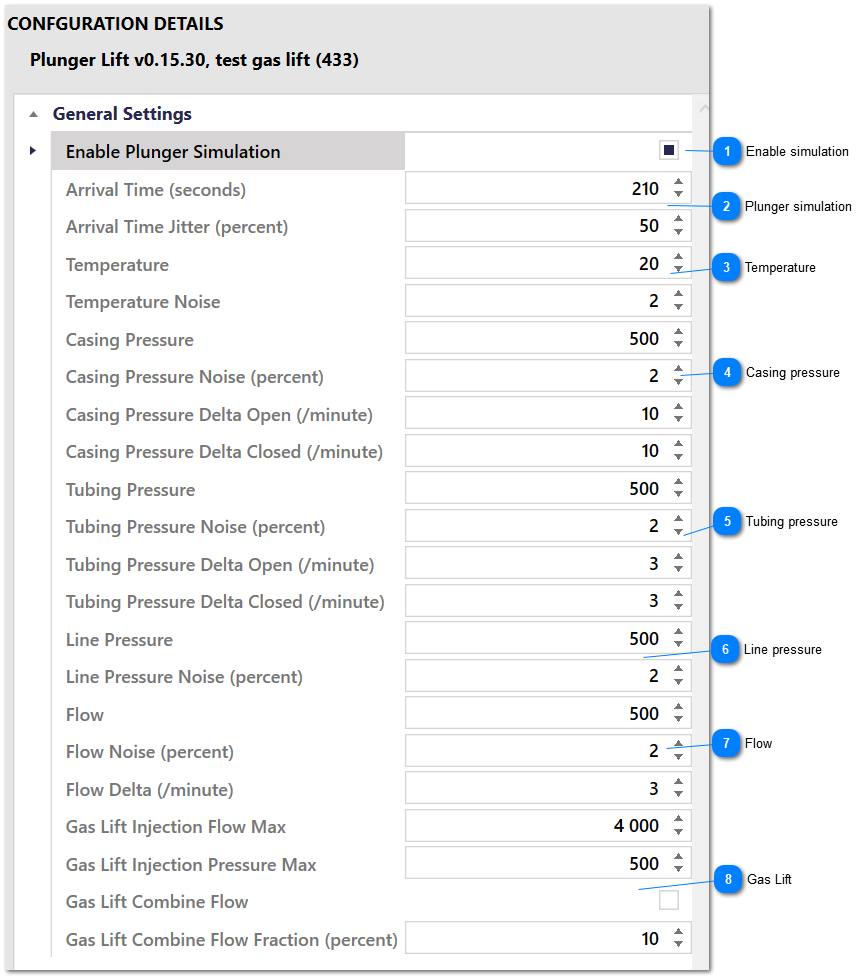
Simulation Settings - Configuration Parameters
Enable simulation
Select this setting to enable this entire set of Simulation settings. The name is unclear and implies that it only enables plunger simulation, but this is not the case.
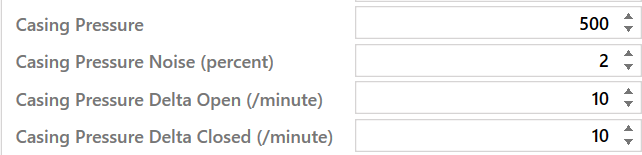
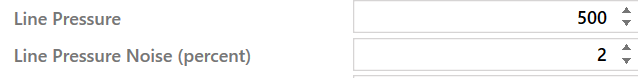
Use these settings to simulate the casing pressure. The Delta allows you to simulate changing values depending on the state of the application and the sales valve. The simulated value will always be continuous and will not jump when the valve opens or closes.
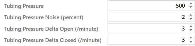
Use these settings to simulate the tubing pressure. The Delta allows you to simulate changing values depending on the state of the application and the sales valve. The simulated value will always be continuous and will not jump when the valve opens or closes.
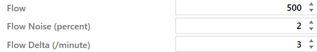
Use these settings to simulate flow. The flow is always 0 when the sales valve is closed and the well is shut in. Flow jumps to the simulated value when the plunger arrives and then declines by the Delta value.
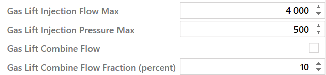
Use these settings to simulate gas lift. The injection flow rate will be calculated as the value of Gas Lift Injection Flow Max multiplied by the fraction that the injection valve is open. The injection pressure will be calculated as the value of Gas Lift Injection Pressure Max multiplied by the fraction that the injection valve is open.
Select the Gas Lift Combine Flow option to add the injected gas flow rate to the simulated well flow rate. Use the Gas Lift Combine Flow Fraction parameter to add just a fraction of the injected gas flow rate to the simulated well flow rate,