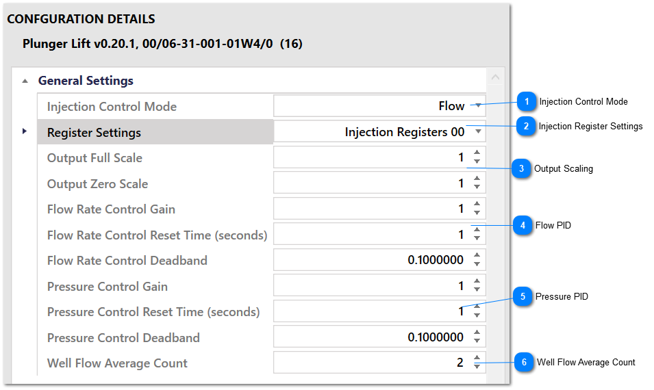
This group holds settings for the PID control blocks that are used to accurately control the injection valve position when injection is active. These settings mirror the settings for PID function blocks in Telepace logic.
Injection Control Mode
Use this setting to chose the control mode for the valve control PID. Options are Flow and Flow With Pressure Override.
When Flow is chosen, the PID loop will ignore the pressure in the injection line. When Flow with Pressure Override is selected, the PID will switch from flow control to pressure control when the pressure in the injection line exceeds the value of the Injection Pressure Set Point control parameter. The system will switch back to flow control if the value of the Injection Flow Set Point control parameter is exceeded by the actual injection flow when controlling via pressure.
Use this setting to configure the number of samples that are averaged to calculate the flow from the well. Averaging can be used to reject noise in the well flow measurement. This averaged value of well flow is only used in the gas lift program when the injection flow rate set point is calculated using critical flow.
The modbus register that holds the flow from the well is read once per second, and is configured in the Input/Output Modbus Register Settings group.