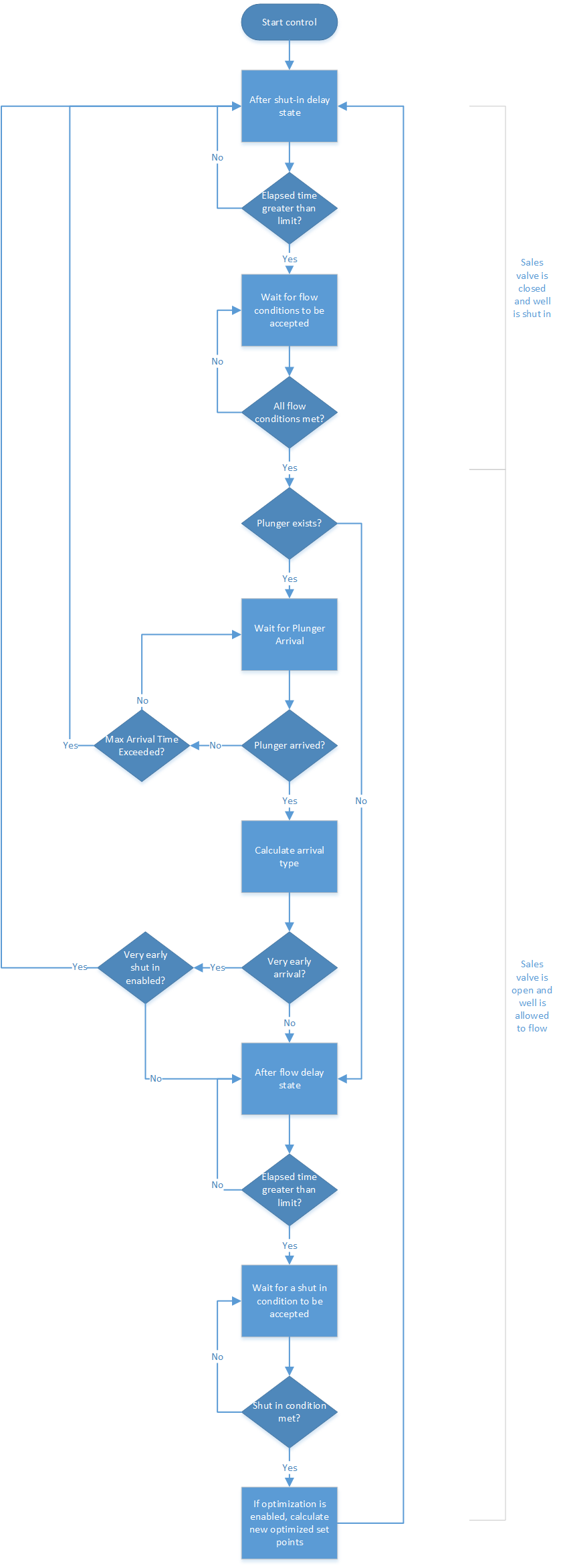
A simplified flow chart of the control loop is shown below. Some details are omitted for the sake of clarity. Each plunger control loop operates independently, however, each plunger control loop follows the same algorithm.
It's not shown on the flow chart, but the Reset command, Protection Settings, Manual Override command and Pause command are checked every cycle, before the normal control algorithm executes. Protection Settings and commands take precedence over the automatic control algorithm.
Once a Protection Setting has been trigged, the only way to exit the Protected state is to manually issue a Reset command.
All enabled Flow Conditions must be met for the control Algorithm to open the sales valve and let the well flow (logical AND). Any enabled Shut In condition being met will cause the sales valve to be closed and the well to be shut in (logical OR).
Exiting from the Protected state will cause the control algorithm to be completely reinitialized.